HVAC Systems Fundamentals are essential for understanding how heating, ventilation, and air conditioning work together to create comfortable and efficient building environments.
1. Introduction
HVAC (Heating, Ventilation, and Air Conditioning) is the backbone of every comfortable, healthy indoor environment—from residential homes to massive commercial buildings, hospitals, data centers, and industrial facilities. Yet despite its critical importance, many professionals and property owners don’t fully understand how HVAC systems work, what components matter most, or why proper design and maintenance are essential.
This comprehensive 10,000+ word guide breaks down HVAC fundamentals from first principles. Whether you’re an MEP engineer designing a new system, an HVAC technician troubleshooting an existing installation, a facility manager responsible for building operations, or a homeowner trying to understand your air conditioning bill—this guide will give you the knowledge to ask better questions, make smarter decisions, and ensure your indoor environments are comfortable, efficient, and compliant with modern building codes.
Table of Contents
2. What is HVAC? Definition & Purpose
Definition
HVAC stands for:
- H = Heating (generating and distributing warmth in winter)
- V = Ventilation (providing fresh outdoor air and removing stale indoor air)
- A = Air Conditioning (cooling and dehumidifying air in summer)
- C = Conditioning (treating air to meet comfort, health, and code requirements)
In essence, HVAC is a system of interconnected mechanical, electrical, and control components designed to maintain comfort and indoor air quality in buildings while using energy efficiently.
Primary Purposes of HVAC Systems
- Thermal Comfort
- Maintain indoor air temperature within an acceptable range (typically 68–76°F in winter, 72–78°F in summer)
- Respond to seasonal changes, time of day, and occupancy variations
- Prevent extreme temperatures that cause discomfort or health risks
- Indoor Air Quality (IAQ)
- Provide fresh outdoor air at rates specified by ASHRAE 62.1 (commercial) or 62.2 (residential)
- Remove indoor pollutants, odors, CO₂, and volatile organic compounds (VOCs)
- Control humidity within healthy ranges (30–60% relative humidity for most spaces)
- Filter particulates (dust, pollen, allergens) to protect occupant health
- Moisture Management
- Remove excess humidity in summer to prevent mold, condensation, and moisture damage
- Maintain appropriate humidity in winter to prevent dry skin, static electricity, and material shrinkage
- Protect building structure from water damage through proper dehumidification
- Code Compliance
- Meet minimum ventilation requirements per ASHRAE 62.1/62.2
- Comply with energy codes (IECC, ASHRAE 90.1)
- Satisfy life safety codes (smoke control, pressurization of stairwells)
- Meet accessibility and occupancy-type-specific standards
- Energy Efficiency & Sustainability
- Minimize annual operating costs through efficient equipment and smart controls
- Reduce carbon footprint via low-refrigerant alternatives and energy recovery
- Support net-zero and LEED building goals
3. The Three Pillars of HVAC: Heating, Cooling, Ventilation
Understanding HVAC requires understanding these three interconnected functions.
3.1 Heating: Keeping Buildings Warm
Purpose: Maintain indoor temperature above the outdoor design temperature in winter.
Heating Methods:
- Furnace (Gas/Oil)
- Combusts natural gas or oil to generate heat
- Transfers heat to air via a heat exchanger
- Hot air is blown through ductwork to rooms
- Efficiency: 80–98% AFUE (Annual Fuel Utilization Efficiency)
- Common in residential and small commercial buildings
- Electric Resistance Heat
- Uses electric coils (like a toaster) to generate heat directly
- Simplest but least efficient method (100% electrical to heat conversion, but high operating cost)
- Often used as backup heat for heat pumps
- Heat Pump
- Reverses the cooling cycle to extract heat from outside air (or ground) and move it indoors
- COP (Coefficient of Performance) typically 2–4, meaning 2–4 units of heat for every 1 unit of electricity input
- More efficient than electric resistance; increasingly popular in cold climates
- Types: Air-source, ground-source (geothermal), water-source
- Boiler + Radiant/Hydronic System
- Heats water (or steam) and distributes via pipes to radiators, baseboard, or radiant floor
- Very efficient and provides consistent comfort
- Common in older buildings and European designs
- Solar Heating
- Passive solar (building orientation, thermal mass) or active solar (solar collectors)
- Gaining traction in net-zero designs
Key Principle: Heat always flows from hot to cold. A heating system’s job is to generate or move heat from a source (furnace, outdoor air, ground) into the building interior.
3.2 Cooling: Air Conditioning & Dehumidification
Purpose: Maintain indoor temperature below the outdoor design temperature in summer and remove excess moisture.
Cooling Methods:
- Vapor-Compression Air Conditioning (Most Common)
- Uses a refrigerant that cycles between liquid and gas states
- Absorbs heat at the evaporator (indoors) and rejects heat at the condenser (outdoors)
- COP typically 2–3 for air-cooled units; 3–5 for water-cooled chillers
- Types: Window AC, split system (indoor + outdoor units), central AC with furnace, chiller plant
- Chilled Water System
- Central chiller produces cold water (45–55°F)
- Water is pumped through air handlers or fan coils in each zone
- Condenser heat is rejected via cooling tower (water-cooled) or direct to outdoor air (air-cooled)
- Ideal for large buildings with multiple zones
- Evaporative Cooling (Swamp Cooler)
- Uses water evaporation to cool air (natural refrigeration)
- Only effective in dry climates; cannot maintain humidity
- Very low operating cost but limited application
- Free Cooling / Economizer
- Uses cold outdoor air directly to cool the building during mild weather (spring/fall)
- Reduces or eliminates mechanical cooling load
- Can achieve 30–50% annual energy savings in moderate climates
- Radiant Cooling
- Chilled water circulates through pipes in ceiling, floor, or walls
- Surface absorbs heat from occupants and interior loads
- Very efficient and quiet; increasingly popular in commercial buildings
Key Principle: Cooling systems remove heat from the building interior and reject it outdoors. The refrigeration cycle is the fundamental mechanism.
3.3 Ventilation: Fresh Air & Indoor Air Quality
Purpose: Provide outdoor air to replace stale indoor air, remove contaminants, and maintain acceptable CO₂ levels.
Ventilation Methods:
- Natural Ventilation
- Wind and temperature difference (stack effect) drive outdoor air through openable windows
- Simple, no energy cost, but unpredictable and weather-dependent
- Limited to mild seasons and buildings designed for it
- Mechanical Ventilation
- Powered fan (blower) pulls outdoor air, conditions it, and distributes via ductwork
- Predictable, controllable, allows filtering and humidity control
- Required in sealed buildings and areas with poor outdoor air quality
- Balanced Ventilation
- Equal amount of outdoor air intake and exhaust removal
- Maintains neutral building pressure
- Most common in modern buildings
- Positive Pressure Ventilation
- More outdoor air intake than exhaust
- Pressurizes building to prevent outside air infiltration
- Used in hospitals, cleanrooms, and humid climates
- Negative Pressure Ventilation
- More exhaust than intake
- Prevents interior odors/contaminants from escaping
- Used in bathrooms, kitchens, lab fume hoods, isolation rooms
Ventilation Standards:
- ASHRAE 62.1: Commercial buildings minimum CFM based on occupancy and space type
- Example: Office = 15 CFM per person + 0.06 CFM per sq ft
- Example: Retail = 0.30 CFM per sq ft (no per-person component)
- ASHRAE 62.2: Residential homes minimum CFM
- Whole-house: (0.03 × sq ft) + (7.5 × # bedrooms)
- Example: 2,000 sq ft, 3 bedrooms = 82.5 CFM minimum
Key Principle: Adequate ventilation dilutes indoor pollutants (CO₂, odors, VOCs, pathogens) to acceptable levels. Higher ventilation = better IAQ but higher energy cost.
4. HVAC System Components Explained
Every HVAC system comprises several key mechanical and electrical components working in concert.
4.1 Cooling System Components
Compressor
- Pumps refrigerant vapor from evaporator to condenser
- Increases pressure and temperature
- Heart of the cooling system
- Types: Reciprocating, scroll, screw, rotary (size/application dependent)
Condenser Coil
- Heat exchanger where high-pressure refrigerant releases heat to outdoor air (or water)
- Refrigerant condenses from vapor to liquid
- Located in outdoor unit (air-cooled) or cooling tower basin (water-cooled)
Condenser Fan/Pump
- Blower fan (air-cooled) moves outdoor air across condenser coil to absorb heat
- Or pump (water-cooled) circulates cool water from cooling tower through condenser
Expansion Device (TXV or Orifice)
- Throttles high-pressure liquid refrigerant to low pressure
- Controls flow to maintain proper superheat in evaporator
- Types: Thermostatic expansion valve (TXV) or fixed orifice
Evaporator Coil
- Heat exchanger where low-pressure refrigerant absorbs heat from indoor air
- Refrigerant evaporates from liquid to vapor
- Located in air handler or furnace (residential) or chilled water system (commercial)
Air Handler / Blower
- Powered fan that circulates indoor air across evaporator coil
- Cooled air is distributed via supply ductwork to occupied spaces
- Also removes moisture (dehumidification)
Supply/Return Ductwork
- Distributes cooled air to rooms (supply ducts)
- Collects warm return air from rooms back to unit (return ducts)
- Must be sealed and insulated to maintain efficiency
Thermostat & Controls
- Sensors monitor temperature and humidity
- Signal system to turn on/off based on setpoint (e.g., “cool to 75°F”)
- Modern thermostats include remote monitoring, scheduling, and AI optimization
Refrigerant Lines
- Copper tubing connects outdoor and indoor units
- Suction line (return vapor), discharge line (high-pressure vapor), liquid line
- Must be insulated to prevent heat loss/gain
4.2 Heating System Components (Furnace-Based)
Furnace / Heat Exchanger
- Burns fuel (natural gas, oil) or generates heat electrically
- Transfers heat to air stream
- Efficiency 80–98% depending on age and type
Gas Valve & Ignition
- Controls fuel flow and ignition
- Electronic ignition (modern) or pilot light (older)
- Safety shutoff if no flame is detected
Blower Motor
- Same as cooling system; circulates air across heat exchanger
- Controlled by thermostat
Ductwork & Registers
- Distributes warm air to rooms
- Return air completes the cycle
Thermostat & Controls
- Calls for heat when indoor temp drops below setpoint
- Stage 1 = furnace, Stage 2 = electric heat (if heat pump)
4.3 Ventilation Components
Outdoor Air Intake
- Damper-controlled opening on roof or side of building
- Allows fresh outdoor air into return ductwork
- Screened to prevent debris/pests
Exhaust Air Outlet
- Return air not recirculated is exhausted outdoors
- Prevents building pressurization
Filters
- MERV 8–13 for standard comfort; MERV 13+ for better IAQ or allergy relief
- Removes dust, pollen, allergens
- Requires regular replacement (monthly to quarterly)
Dampers
- Motorized dampers modulate outdoor vs recirculated air proportion
- Economizer damper opens when outdoor air is cold/cool enough for free cooling
Energy Recovery (HRV/ERV)
- Heat Recovery Ventilator (HRV): Captures sensible heat from exhaust air
- Energy Recovery Ventilator (ERV): Captures sensible + latent (moisture) heat
- Can reduce ventilation energy penalty by 40–70%
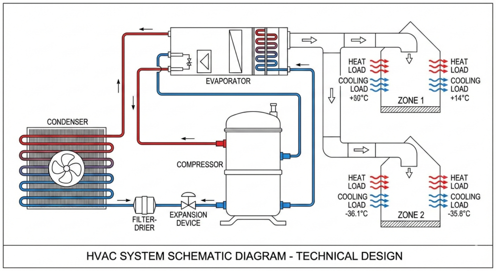
5. The Refrigeration Cycle: How Cooling Works
The refrigeration cycle is the fundamental process that makes air conditioning possible. Understanding it is essential for HVAC fundamentals.
5.1 The Four-Step Cycle
Step 1: Evaporation (Evaporator Coil)
- Low-pressure refrigerant liquid enters the evaporator at ~40°F
- Indoor air (75°F) passes over the coil
- Heat flows from warm air into cold refrigerant
- Refrigerant absorbs this heat and evaporates (boils) into vapor form
- Air leaving the coil is now cool (~55°F) and dehumidified
Step 2: Compression (Compressor)
- Low-pressure vapor (40°F) exits evaporator into compressor
- Compressor mechanically pumps the vapor, increasing its pressure and temperature
- Vapor pressure rises from ~70 psi to ~300 psi
- Vapor temperature rises from 40°F to ~150°F (superheated vapor)
Step 3: Condensation (Condenser Coil)
- High-pressure, hot vapor enters the outdoor condenser coil
- Outdoor air (95°F in summer) passes over the coil
- Because the vapor is hotter than outdoor air, heat flows from refrigerant to outdoor air
- Refrigerant cools and condenses (liquefies) back to liquid form
- Liquid exits condenser at ~100°F, still at high pressure (~300 psi)
Step 4: Expansion (Expansion Device)
- High-pressure liquid (100°F, 300 psi) enters the expansion device (TXV)
- TXV throttles the refrigerant, reducing pressure and temperature
- Liquid pressure drops to ~70 psi
- Temperature drops to ~40°F (some liquid flashes to vapor, creating a cold liquid-vapor mixture)
- This cold mixture re-enters the evaporator, and the cycle repeats
5.2 Energy Balance
The refrigeration cycle demonstrates the law of energy conservation:
Heat absorbed at evaporator + Work input at compressor = Heat rejected at condenser
In equation form:Qevap+Wcomp=Qcond
Example (3-ton AC unit):
- Heat absorbed indoors: 36,000 BTU/hr (3 tons × 12,000 BTU/ton)
- Compressor work: ~12,000 BTU/hr (equivalent to ~3.5 kW)
- Heat rejected outdoors: 48,000 BTU/hr
- COP (efficiency): 36,000 ÷ 12,000 = 3.0 (3 units of heat moved per 1 unit of energy input)
5.3 Refrigerant Selection
Modern refrigerants must balance performance, safety, cost, and environmental impact.
Common Refrigerants:
- R-22 (Freon): Old standard; being phased out due to ozone depletion (Montreal Protocol)
- R-410A: Replacement for R-22; high pressure, good performance; still widely used but being phased down
- R-32: Lower pressure, lower GWP; replacement for R-410A
- R-290 (Propane): Natural refrigerant; excellent efficiency but flammable (special handling)
- CO₂ (R-744): Natural, non-toxic, non-flammable; used in some heat pumps; requires higher pressure
- R-513A, R-454B: Low-GWP (global warming potential) alternatives emerging
Key Property: Saturation Temperature
- At a given pressure, refrigerant has a specific saturation temperature where it boils/condenses
- R-410A at 70 psi ~ 0°F
- R-410A at 300 psi ~ 120°F
- Engineers use pressure-temperature charts to diagnose system performance
6. The Heating Cycle: How Heat is Generated & Distributed
6.1 Furnace Heating (Natural Gas)
Four-Step Process:
- Combustion
- Natural gas mixes with air from a blower
- Ignition (electronic spark or pilot light) ignites the mixture
- Controlled flame burns inside the heat exchanger
- Heat Transfer
- Flame heats metal walls of the heat exchanger to ~700°F
- Cold return air (70°F) from the house is pulled across the hot heat exchanger by the blower
- Air absorbs heat and exits as warm supply air (~130–150°F)
- Efficiency Considerations
- Non-condensing furnaces (80% AFUE): Exhaust gases escape as hot vapor; heat is lost
- Condensing furnaces (90–98% AFUE): Cool exhaust gases to recover latent heat from water vapor; squeeze ~10–15% more efficiency
- Distribution
- Warm air flows through supply ductwork to registers in rooms
- Cool return air from rooms is pulled back to furnace, and cycle repeats
6.2 Heat Pump Heating (Reverse Cycle)
Instead of generating heat via combustion, a heat pump moves heat from outdoors to indoors using the refrigeration cycle in reverse.
Process:
- Outdoor Heat Exchange (Outdoor Coil Now Acts as Evaporator)
- Outdoor air temperature: 35°F (winter design)
- Low-pressure refrigerant at 20°F passes through outdoor coil
- Even at 35°F outdoor air is warmer than 20°F refrigerant
- Heat flows from outdoor air into refrigerant
- Refrigerant evaporates and is drawn into compressor
- Compression
- Compressor raises pressure and temperature to ~120°F (high-pressure vapor)
- Indoor Heat Exchange (Indoor Coil Now Acts as Condenser)
- Hot refrigerant at 120°F enters indoor coil
- Indoor air at 68°F passes over the coil
- Heat flows from refrigerant to indoor air (heating the house)
- Refrigerant condenses to liquid
- Expansion
- Liquid is throttled back to low pressure and flows to outdoor coil
- Cycle repeats
Efficiency:
- COP typically 2–3 in heating mode (2–3 units of heat moved per unit of energy)
- Much more efficient than electric resistance heat (COP = 1)
- Performance degrades as outdoor temperature drops; at ~15°F or colder, most heat pumps switch to electric backup heat
Advantage: One system provides both heating and cooling year-round.
7. Ventilation Fundamentals & Indoor Air Quality
7.1 Why Ventilation Matters
Indoor air contains CO₂ from occupant respiration, odors, VOCs from furniture and cleaning products, dust, pollen, and potentially pathogens (especially post-COVID).
Without ventilation:
- CO₂ levels exceed 1,000 ppm (outdoor baseline ~400 ppm)
- Cognitive function declines (Harvard study showed 101% improvement with higher ventilation)
- Mold and mildew grow from excess moisture
- Odors become unbearable
With adequate ventilation:
- CO₂ controlled to <800 ppm (ASHRAE 62.1 target)
- Pollutants diluted to safe levels
- Moisture managed to prevent condensation and mold
- Occupants report better health, sleep, and productivity
7.2 Ventilation Rate Calculation
ASHRAE 62.1 Procedure (Commercial):CFM=(Rp×Occupants)+(Ra×Area)
Where:
- Rp = CFM per person (e.g., 15 CFM/person for offices)
- Ra = CFM per 100 sq ft (e.g., 0.06 CFM/sq ft for offices)
- Occupants = expected number of people
- Area = space floor area in sq ft
Example: 50-person office in 2,500 sq ft
- Per person: 50 × 15 = 750 CFM
- Per area: 2,500 × 0.06 = 150 CFM
- Total: 900 CFM minimum
ASHRAE 62.2 (Residential):CFM=(0.03×Area)+(7.5×Bedrooms)
Example: 2,000 sq ft, 3-bedroom home
- CFM = (0.03 × 2,000) + (7.5 × 3) = 60 + 22.5 = 82.5 CFM minimum
7.3 Humidity Control
Comfortable humidity range: 30–60% relative humidity (RH)
Too Low (<30% RH):
- Dry skin, cracked lips, bloody nose
- Static electricity shocks
- Wood shrinkage and warping
- Increased airborne virus transmission (dry air aids pathogen spread)
Too High (>60% RH):
- Mold and mildew growth
- Dust mite proliferation
- Condensation on windows and cold surfaces
- Moisture damage to building materials
Summer Humidity Control:
- AC system naturally dehumidifies as cool air condenses moisture
- Air leaving evaporator is cold (~55°F) and dry (~30% RH)
- When air reheats in ductwork/room, RH remains low (relative to the warmer air)
Winter Humidity Control:
- Furnace heating dries indoor air
- Add humidifier to maintain 30–40% RH (prevents dry air issues)
- Ventilation must still remove excess moisture from occupants/cooking/showers
8. HVAC System Types & Classifications
HVAC systems are classified by configuration, capacity, and application.
8.1 By Configuration
Central Systems (Ducted)
- Single large unit (furnace/AC or air handler) conditions all air centrally
- Conditioned air distributed via ducts to multiple rooms
- Common in residential, small commercial
- Advantages: Efficient, centralized maintenance, good filtering
- Disadvantages: Large ductwork space requirement, duct losses, single zone control
Distributed Systems (Ductless)
- Multiple small units (mini-splits, window ACs) serving individual rooms/zones
- No ductwork required
- Common in retrofits, apartments, offices with individual control needs
- Advantages: Zone control, no duct loss, easier installation, quiet
- Disadvantages: Higher equipment cost, more outdoor units, potential noise
Hybrid Systems
- Combination of central + distributed (e.g., central ventilation + ductless cooling)
- Growing trend for efficiency and flexibility
8.2 By Equipment Type
Window Air Conditioner
- Self-contained unit mounted in window
- Cools single room, 5,000–25,000 BTU
- Inexpensive, simple, no installation
- Noisy, blocks window, limited efficiency
Split System (1:1)
- Indoor unit (wall-mounted or ceiling-mounted) + outdoor unit
- Refrigerant lines connect the two
- 9,000–36,000 BTU typical
- Quiet, efficient, good for apartments/retrofits
Multi-Split System (1:Many)
- One outdoor unit connects to multiple indoor units
- Each indoor unit independently controlled
- Efficient heat recovery in winter (some indoor units heat while others cool)
- Common in VRF systems
Central AC + Furnace (Most Common Residential)
- Furnace (heating) + AC condenser (cooling) + air handler (circulation)
- Single ductwork serves both heating and cooling
- Efficient and economical for single-family homes
Packaged Rooftop Unit (RTU)
- All components in single outdoor unit on roof
- Supply/return ductwork only
- Common in small commercial buildings and retail
- Advantages: Simple, economical
- Disadvantages: Outdoor noise, single zone, shorter lifespan (harsh outdoor conditions)
Chiller Plant (Large Commercial)
- Central chiller produces 45–55°F chilled water
- Water pumped to multiple air handlers or fan coils throughout building
- Cooling tower rejects condenser heat
- Each zone has its own air handler and zone control
- Very flexible, scalable, efficient
8.3 By Capacity
- Residential: 1–5 tons (10,000–60,000 BTU/hr)
- Small Commercial: 5–30 tons (60,000–360,000 BTU/hr)
- Large Commercial: 30–500+ tons (multiple chillers)
9. Psychrometrics: Air Properties & Comfort
Psychrometrics is the study of moist air properties. The psychrometric chart is the single most important tool in HVAC design.
9.1 Key Air Properties
Dry Bulb Temperature (DB or DBT)
- Regular temperature measured by a standard thermometer
- Horizontal axis on psychrometric chart
- Range: -50°F to 150°F typical
Wet Bulb Temperature (WB or WBT)
- Temperature read by a thermometer with a wet cloth wrapped around the bulb
- Accounts for evaporative cooling effect
- Lower than dry bulb (except when RH = 100%)
- Vertical axis on psychrometric chart
Relative Humidity (RH)
- Percentage of moisture in air vs. maximum possible at that temperature
- Diagonal lines on psychrometric chart
- 0% = completely dry, 100% = saturated (dew point equals dry bulb)
Dew Point Temperature
- Temperature at which air becomes saturated (100% RH)
- If air is cooled below dew point, moisture condenses
- Example: 70°F, 50% RH → dew point = ~50°F
- Cool air to 50°F → condensation begins
Humidity Ratio (W or Absolute Humidity)
- Grams of water vapor per kilogram of dry air
- Constant along diagonal lines on psychrometric chart
- Independent of temperature (if no water added/removed)
Enthalpy (h)
- Total heat content of moist air (sensible + latent heat)
- Measured in BTU per pound of dry air
- Used to calculate energy changes in HVAC processes
9.2 Using the Psychrometric Chart
Finding State of Air:
- Locate dry bulb temperature on horizontal axis (bottom)
- Locate relative humidity diagonal line
- Intersection = state point
- Read wet bulb (diagonal), dew point (vertical), humidity ratio (vertical), and enthalpy
Cooling Process (Summer AC):
- Start: Outdoor air at 95°F, 60% RH (supply air to AC)
- Air passes through evaporator coil at 55°F
- Cooling follows vertical line downward (reducing dry bulb, humidity ratio constant until RH = 100%)
- At 55°F, RH = 100%, moisture condenses out (dehumidification)
- Dry bulb continues to drop; humidity ratio decreases (moisture leaves the air)
- Exit: 55°F, ~95% RH (saturated)
- This air is reheated to 70°F in ductwork → 70°F, ~30% RH (dry supply air)
Heating Process (Winter Furnace):
- Start: 35°F outdoor air, 70% RH
- Outdoor air is mixed with return air (70°F, 35% RH)
- Mixed air heated in furnace to 130°F
- Heating follows vertical line upward (dry bulb increases, humidity ratio constant)
- Supply air: 130°F, ~5% RH (very dry)
- This dry air evaporates moisture from skin → occupant discomfort
- Solution: Add humidifier to raise humidity ratio before heating
9.3 Comfort Zone (ASHRAE 55)
ASHRAE Standard 55 defines the comfort zone—the range of temperature, humidity, and air velocity where 80% of occupants feel comfortable.
Typical Comfort Zone (Winter):
- Dry bulb: 68–74°F
- Relative humidity: 30–60%
- Air velocity: <50 ft/min
Typical Comfort Zone (Summer):
- Dry bulb: 74–78°F
- Relative humidity: 30–60%
- Air velocity: <70 ft/min
Factors affecting comfort:
- Clothing level (affects heat generation from body)
- Activity level (exercise = more heat generation)
- Radiant temperature (cold walls/windows = discomfort even if air temp is correct)
- Air velocity (draughts cause discomfort; too little air feels stuffy)
10. Key Thermodynamic Principles
10.1 First Law of Thermodynamics
Energy is conserved: energy input = energy output + energy storage
In HVAC:Qin+W=Qout+ΔE
- Q_in = Heat input (furnace combustion, solar gain, occupants)
- W = Work input (fan, compressor, pump motors)
- Q_out = Heat output (cooling system rejects heat, occupants lose heat to walls)
- ΔE = Change in building internal energy (temperature change)
10.2 Second Law of Thermodynamics
Heat always flows from hot to cold spontaneously (never the reverse without external work).
HVAC Application:
- AC evaporator must be colder than indoor air for heat to flow into refrigerant
- Furnace heat exchanger must be hotter than return air for heat to flow into air
- If temperature difference is too small, insufficient heat transfer
- Larger ΔT = better heat transfer but less comfort (cold supply air feels draughty)
10.3 Latent vs Sensible Heat
Sensible Heat: Heat that changes air temperature (measurable on thermometer)
- Example: 70°F → 75°F is 5°F sensible temperature change
Latent Heat: Heat that changes the state of matter without changing temperature
- Example: 212°F boiling water remains 212°F while evaporating to steam
- In HVAC: AC removing moisture from air absorbs latent heat without changing dry bulb initially
Sensible Heat Ratio (SHR):SHR=Total Heat LoadSensible Heat Load=Sensible + LatentSensible
- SHR = 0.8 means 80% of cooling goes to temperature reduction, 20% to dehumidification
- Affects coil selection and reheat requirements
10.4 Heat Transfer Mechanisms
Conduction: Heat flows through solid material (e.g., through building walls)
- Rate = U-factor × Area × ΔT
- U-factor (BTUH/sq ft/°F) inversely related to R-value insulation
Convection: Heat transfers between solid surface and moving fluid (air or water)
- Rate = h × Area × ΔT
- h (convection coefficient) depends on fluid velocity, type, temperature
Radiation: Heat transfers via electromagnetic waves (e.g., sun through windows)
- Rate = σ × Area × (T₁⁴ − T₂⁴)
- Important for solar heat gain, human comfort (cold wall radiation)
Example: Summer cooling load includes:
- Conduction through walls/roof (U-factor effect)
- Solar radiation through windows (SHGC effect)
- Convection from outdoor air over building surface
- Internal gains (people, lights, equipment) via convection to air
11. HVAC Design Fundamentals
11.1 The Design Process
- Calculate Loads
- Cooling load (sensible + latent) per room
- Heating load per room
- Ventilation requirements per ASHRAE 62.1/62.2
- Diversity factors (not all rooms peak simultaneously)
- Select Equipment
- Furnace/boiler capacity for peak heating load
- AC/chiller capacity for peak cooling load
- Air handler CFM based on cooling load and target supply air temperature
- Ductwork sized for airflow with acceptable static pressure loss
- Design Distribution
- Ductwork layout for supply and return
- Duct sizing (typically 0.1 in. water column static pressure per 100 ft of duct)
- Diffuser/register selection and location
- Damper placement for zoning
- Control Strategy
- Thermostat location and setpoint
- Single-stage vs. multi-stage heating/cooling
- Ventilation control (fixed, demand-controlled via CO₂)
- Humidity control (humidifier/dehumidifier requirements)
- Commissioning
- Verify airflow (measure CFM with anemometer)
- Check temperatures (supply, return, room)
- Test controls (heating, cooling, fan operation)
- Adjust dampers for balance across rooms
11.2 Design Standards & Practices
ASHRAE 90.1: Energy Standard for Buildings
- Minimum equipment efficiency (SEER 13+, AFUE 90%+, COP 2.5+)
- Ventilation controls (outdoor air dampers, economizer)
- Insulation minimums (walls, ducts, pipes)
- System configuration requirements
ASHRAE 62.1/62.2: Ventilation & Indoor Air Quality
- Minimum outdoor air rates
- Filtration standards (MERV 13 typical)
- Humidity control ranges
- IAQ procedures
SMACNA (Sheet Metal and Air Conditioning Contractors Association):
- Ductwork construction standards (sealing, insulation, support)
- Installation practices
- Commissioning procedures
12. ASHRAE Standards & Building Codes
12.1 Key ASHRAE Standards
ASHRAE 55: Thermal Environmental Conditions for Human Occupancy
- Defines comfort zone for temperature, humidity, air velocity, radiant asymmetry
ASHRAE 62.1: Ventilation for Acceptable Indoor Air Quality (Commercial)
- Minimum outdoor air rates by space type
- Filtration requirements
- Demand-controlled ventilation provisions
ASHRAE 62.2: Ventilation & Acceptable Indoor Air Quality in Residential Buildings
- Whole-house ventilation CFM
- Kitchen exhaust requirements
- Bathroom exhaust requirements
ASHRAE 90.1: Energy Standard for Buildings
- Efficiency levels, controls, system configuration
ASHRAE 170: Design, Testing, Adjustment, Balancing & Commissioning of Healthcare Facilities
- Hospital-specific ventilation, pressurization, and system requirements
12.2 International Building Code (IBC) & Local Codes
- HVAC mechanical requirements (indoor/outdoor air, exhaust)
- Ductwork construction standards
- Boiler/furnace installation standards
- Life safety requirements (stairwell pressurization, smoke control)
- Energy code compliance (usually ASHRAE 90.1 adoption)
13. Common HVAC Mistakes & How to Avoid Them
Mistake 1: Oversizing Equipment
- Problem: Oversized AC short-cycles (runs briefly, shuts off), never reaching full capacity, poor humidity control
- Solution: Size to load via Manual J (residential) or Manual N (commercial), not rule-of-thumb
Mistake 2: Inadequate Ventilation
- Problem: High CO₂ (>1000 ppm), odors, occupant complaints, regulatory violations
- Solution: Calculate per ASHRAE 62.1/62.2, include outdoor air damper and controls
Mistake 3: Poor Ductwork Design
- Problem: Low airflow, unbalanced rooms, noise, high static pressure
- Solution: Size ducts to 0.1 in. w.c./100 ft, seal and insulate, balance with dampers
Mistake 4: No Humidity Control
- Problem: Summer: excess moisture, mold; Winter: dry air, static shocks
- Solution: AC handles summer; add humidifier for winter
Mistake 5: Ignoring Outdoor Air Quality
- Problem: Outdoor air pollution enters building
- Solution: Use MERV 13+ filters, monitor AQI, consider activated carbon filters in polluted areas
14. Troubleshooting HVAC Basics
“My AC Isn’t Cooling Enough”
- Check: Thermostat setting, air filter (clogged?), supply/return airflow balance, refrigerant charge level
- Common causes: Dirty filter, low refrigerant, blower not running, ductwork leakage
“My Furnace Keeps Shutting Off”
- Check: Thermostat, air filter, return duct blockage, limit switch setting
- Common causes: Overheating due to poor return air flow, faulty thermostat, blocked filter
“Uneven Heating/Cooling Between Rooms”
- Check: Dampers, airflow distribution, ductwork balance
- Solution: Manually balance with dampers (increase airflow to cold rooms, decrease to hot rooms)
“High Electric Bills in Summer”
- Check: Thermostat setpoint, AC efficiency (SEER), ductwork leakage, outdoor air intake
- Solution: Raise setpoint 2–3°F, seal ducts, consider efficiency upgrade
15. Future of HVAC Technology
Emerging Technologies
- Heat Pump Advancement
- Cold-climate heat pumps (operate down to -20°F)
- Hybrid heat pump + furnace for seamless efficiency
- Electrification trend (replacing gas furnaces)
- Smart Controls & AI
- Machine learning predicts occupancy and adjusts temperature/ventilation
- Automated demand-response to grid signals
- Integration with smart home systems
- Low-GWP Refrigerants
- Transition from R-410A to R-32, R-454B (lower global warming potential)
- Natural refrigerants (propane, CO₂) gaining traction
- Radiant & Hybrid Systems
- Chilled ceilings + DOAS combination (efficiency + comfort)
- Reduced ductwork, lower energy
- IAQ Advancement
- UV-C disinfection of coils/ducts
- Advanced air cleaning (HEPA, photocatalytic)
- Real-time air quality monitoring (CO₂, VOC sensors)
- Renewable Integration
- Solar-assisted cooling and heating
- Thermal energy storage for peak shaving
- District cooling/heating networks
16. Conclusion & Key Takeaways
HVAC Systems Fundamentals provides the foundation for understanding comfortable, healthy, efficient indoor environments.
Key Principles Recap
✅ HVAC = Heating + Ventilation + Air Conditioning – Three interconnected functions
✅ Refrigeration cycle – The mechanical basis of cooling (compress → condense → expand → evaporate)
✅ Heat always flows from hot to cold – Design equipment to maximize this flow for efficiency
✅ Ventilation dilutes pollutants – Adequate outdoor air is non-negotiable for occupant health
✅ Psychrometrics quantifies air properties – The chart is your HVAC design tool
✅ Standards govern minimum performance – ASHRAE 62.1, 90.1, and local codes aren’t optional
✅ Proper design beats oversizing – Bigger equipment wastes energy and creates discomfort
✅ Maintenance matters – Filter changes, refrigerant checks, and seasonal prep extend equipment life
Next Steps
- For homeowners: Check your furnace/AC filter monthly, ensure thermostat is working, don’t ignore strange noises
- For technicians: Understand your tools (psychrometric chart, pressure-temperature relationships, electrical basics)
- For engineers: Master Manual J/N load calculations, ASHRAE standards, and system design principles
- For facility managers: Implement preventive maintenance, monitor energy bills, invest in controls upgrades
Further Learning
- Enroll in HVAC fundamentals course (Coursera, ASHRAE training)
- Study ASHRAE Handbook – Fundamentals (industry bible)
- Join local ASHRAE chapter for networking and continuing education
- Practice with load calculation software (Wrightsoft Right-Suite, CoolCalc)
Related Articles on Famcod
- Air Changes per Hour (ACH) Calculations: Complete Guide
- Cooling Load Calculation: Manual J vs Manual N
- Heating Load Calculation: Complete Guide
- Blower Motor Selection Guide: PSC vs ECM
- Psychrometrics Chart Mastery for HVAC Design
- ASHRAE 62.1 Ventilation Standards Simplified